Saturday, April 24, 2010
Friday, April 9, 2010

Today is the practice day. Basically, it is the last day for our team to configurate the main parts of the robot.
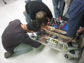
This is the picture of the robot from the bottom view. It is a pnuematic kicker and at the conjunction of pushing stick and the kicker, there is a latch. It takes one second to pull the kicker back in, then use that latch to hold it. Whenever the robot is on the right position to kick the ball, the program will loose the latch. In the last robot functional test, our robot can kick a standard soccer ball 30 feet far that is about one region on the competition field. The student in the picture is trying to find the right position to integrate the hooking system into the robot.
This is a look at the wheels of our robot. Every robot have its own different style. Wheels are the best way to show the unique characteristics of the team. Our weels are 45 degrees to the robot's frame. Of course, we do need to have a special program to run the program so that it can walking as expected.
This is a look at one of the wheel motors. Each of the wheel motors is individually connected to the wireless controller. Therefore, the robot can move to every direction the programmer expects.

This picture shown above is that they just finish configurating the web camera. The motor under the camera can machenically change the direction where the camera faces. It is controlled by the programmer.
The students are screwing the number bars around the robot. The light green stick at the up-right corner is our completed hooking system.Finally, the robot completed. Our team number is 2359 among the red team. The functions of our robot are long-distance kick goaling and hooking the robot at the end of the game so that it can gain more points for the team.
It is the actual competition field. There are three regions. Each one has two robots from red and blue team. The positions for robots are defenser, passer and goaler.
The picture shown above is the example of hooking system performence. The team which complete this performance will be counted two goals.

February 22nd: The control console from which the robot could be operated.

February 22nd: A top view of the robot with circuitry in place and bumpers attached on three sides. At the bottom is the kicker.

February 19th: Chen showing his handiness as he helps take out the pneumatic rod that controlled the kicker movement to be replaced by a tube with a different air capacity.

February 19th: Shown is a picture of the mostly assembled robot only several days before development was to come to a halt. With the robot oriented as seen in the picture, the hooking device can be seen at the bottom. On the right side facing north and south the small silver tube is the storage tank for air pressure. This pressure controls the kicker which is attached to the long silver tube that is going under the robot. At the top center is the brains of the robot. This was actually a modified gaming unit which could be programmed wirelessly and provided the instructions on how the robot was to function and operate all its motors.

February 13th: In the hallway testing the kicker, making sure that it can kick the soccer ball far enough.

February 13th: Taking measurements to make sure everything would fit properly
 February 13th: The attempt at a device to attach the robot to the 7 foot bar along the top of the playing field for the finale. The idea was that an electric motor would turn one of the rubber knobs in a certain direction depending upon what supply voltage was given to it. This would cause the tape measures to either extend or retract. attached to the end of the tape measures was a metal hook which was connected to a winch which would then pull the robot off the ground.
February 13th: A look at the computer representation of the bracket that was designed to hold the battery and air compressor that ran the pneumatic kicking device. This was made out of bent aluminum riveted together.

February 6th: This is a picture showing a student working on an over-sized model of the kicking mechanism that would be deployed on the robot. They used this to get an idea of how the kicker would work in order to properly build smaller scale one to fit on the robot.
Subscribe to:
Comments (Atom)


